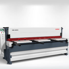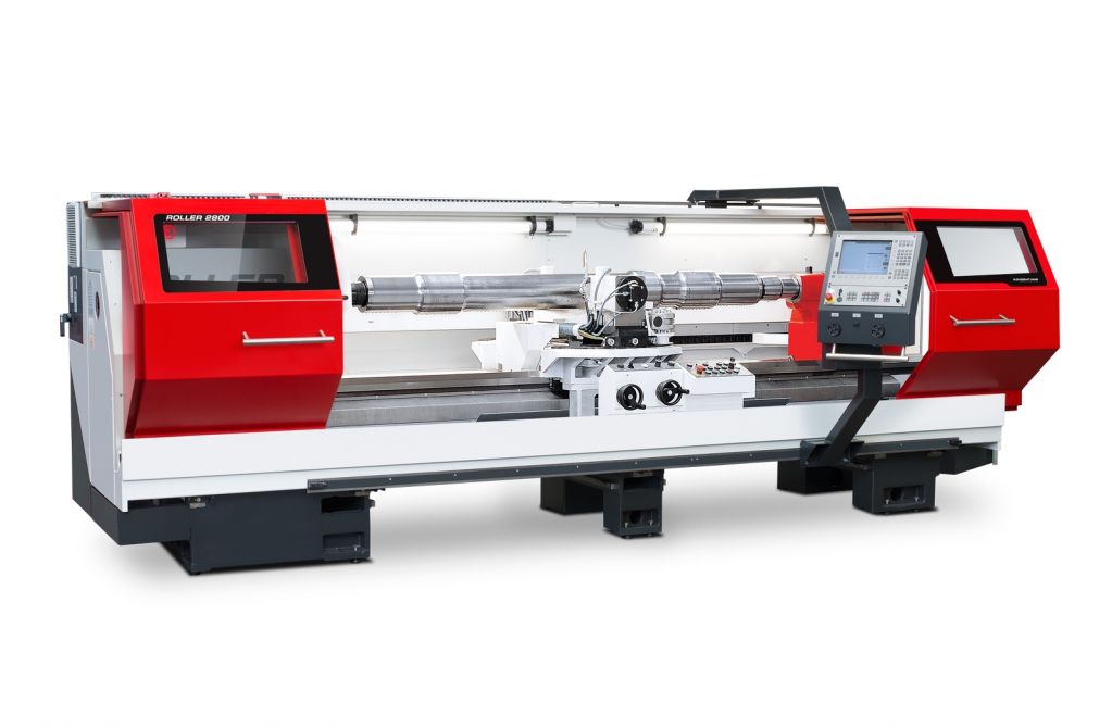
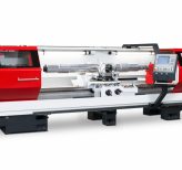
KOVOSVIT ROLLER 2800 CNC Special technologies
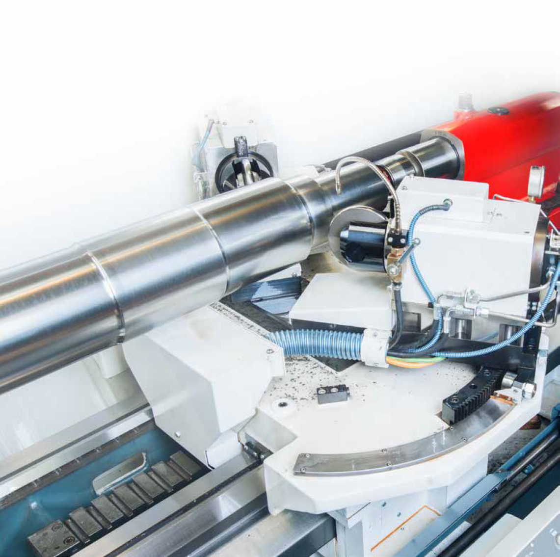
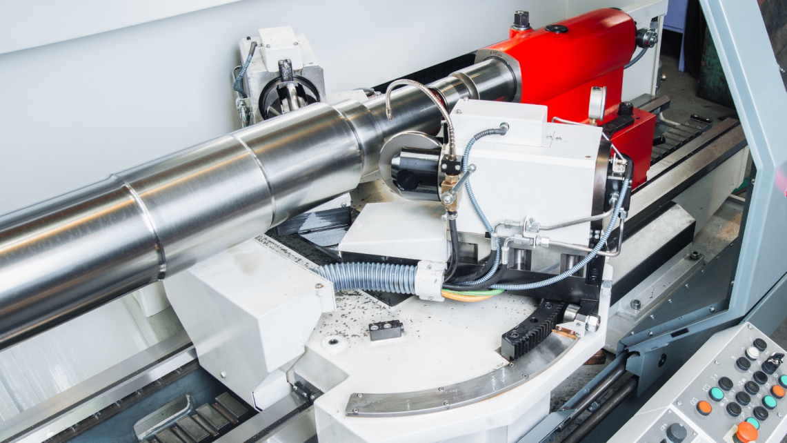
The special ROLLER 2800 CNC is the skeleton of the machine
and is derived from the standard MASTURN 70/3000 CNC lathe
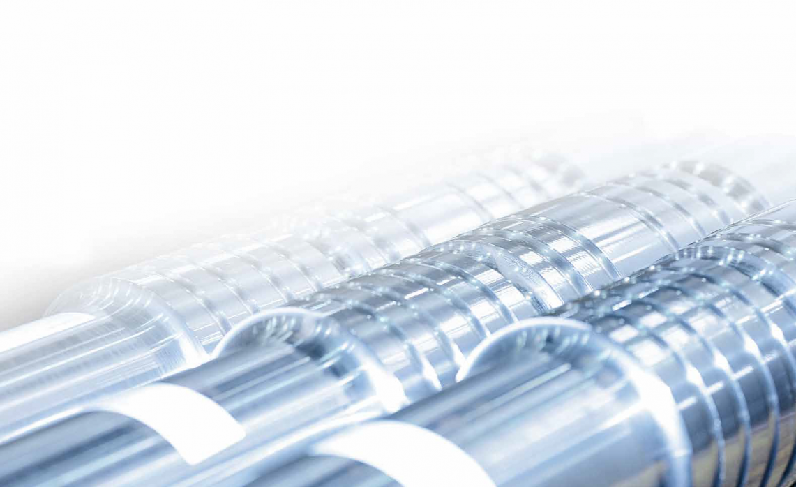
machine. The function is based on cold moulding technology:
the rolling of cylindrical, conical and transition radius areas of
shaft parts, i.e. vehicle axles. This function, along with others,
pre-determines the area of the use of the machine for the
specialized production of parts for use in surface fi xation
technology in a perpendicular direction of the rolling tool to the
surface of the material by means of a mechanism for tilting axis
B by the CNC system.
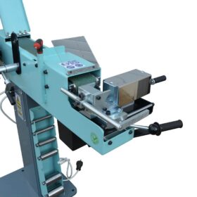
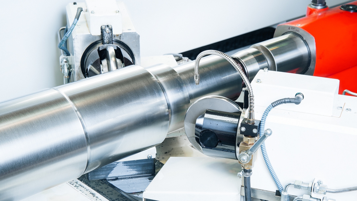
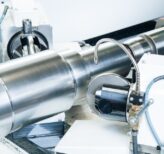
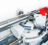
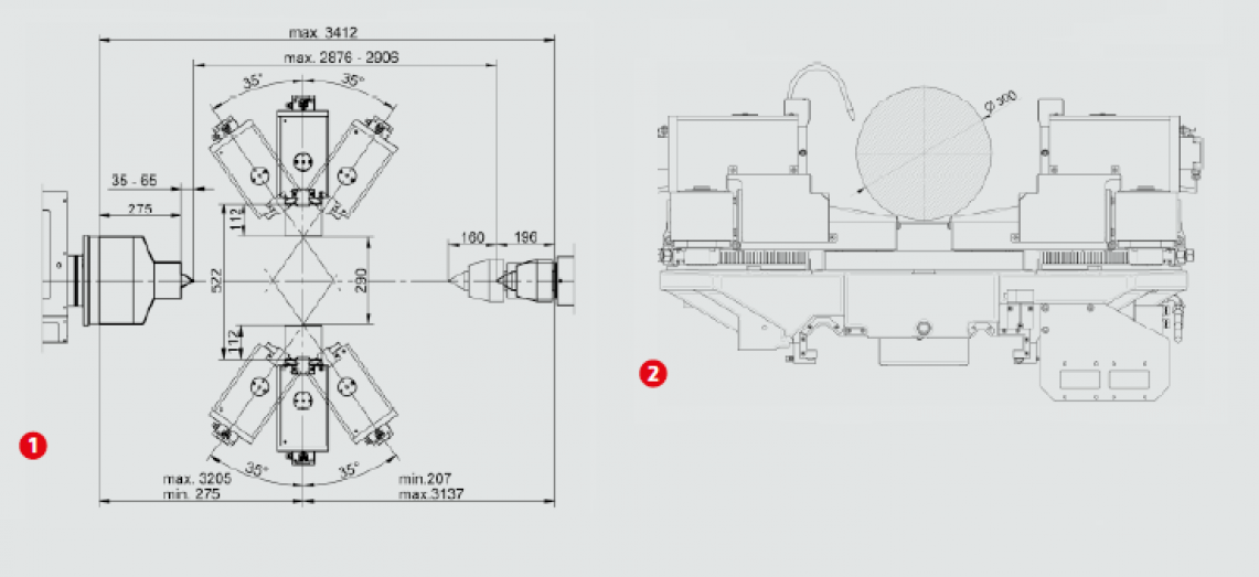
Form rolling equipment is located on the longitudinal saddle.
The saddle moves by means of a CNC controlled axis Z on the
bed of the machine in a longitudinal direction. The movement
in axis X is performed hydraulically by two opposite located
tailstock sleeves for the rolling heads, into which the rolling
tools are clamped. Fluent changes to pressure on the rolling
tools can be changed in the program during the working cycle.
The system enables the indirect independent measurement of
the rolling force and the recording and archiving of data from
the rolling process.
The arrestment of turning the rolling heads in the respective
position is ensured by a drive using self-locking worm gears.
Swing dia. without using of tilting B-axes: 300 mm
Max. power of multi-roller without using of tilting B-axes: 50 kN
Max. workpiece weight: 1 000 Kg
Output S1: 11 kW
 |
|
 |
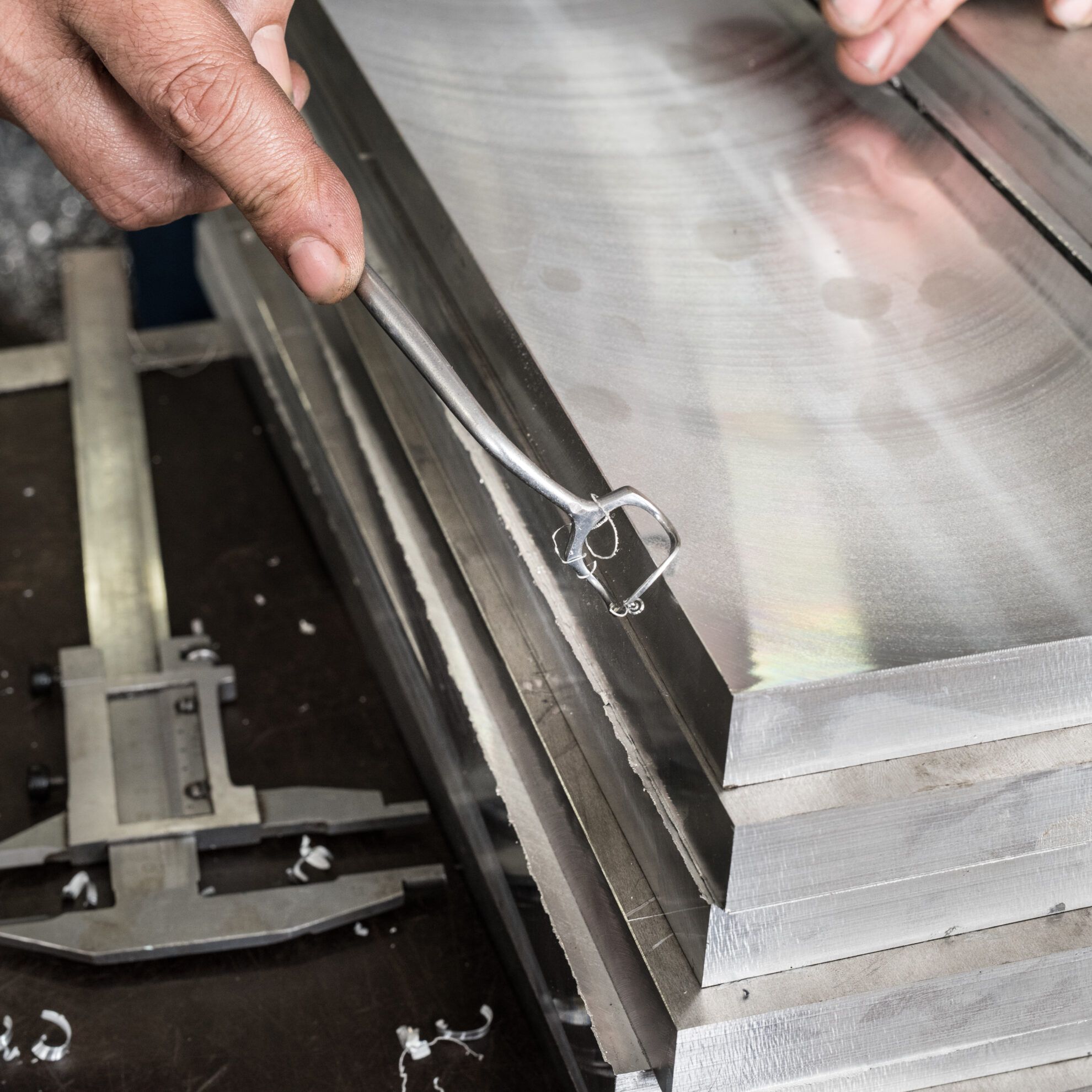
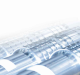
The advantage of a rolled surface is based on achieving a smooth surface by cold moulding the surface layer. With the quality of the tooling it replaces grinding technology, although without the precision of the dimension of the machined area when grinding. Rolling is recommended as a fi nishing operations for the strengthening of surfaces of non-tolerated dimensions or as technology for strengthening the surface layer before the finishing grinding of areas for tolerated dimensions. |
Working space lighting
Röhm 116 Mk6 (604H) movable centre
Calibrating load gauge
Adaptor into spindle Metric 112/Mo 6
Carrier
Lubrication of pulleys
Tube for lubrication oil for rolling oil
Tool kit
Accompanying documentation
The machine is equipped in standard with SIEMENS 840 D system
Lifting equipment 3000
Switch board cooling – air-condition
Adapter
Rolling holder (2 pc set)
Pulleys on request (2 pc set)
Remote diagnostics
Special movable centre
 |
|
|
|
| TECHNICAL DATA | Roller 2800 CNC | |
| Geometric and operating accuracy | ISO 1708 | |
| Swing dia. without using of tilting B-axes | mm | 300 |
| Swing dia. with using of tilting B-axes to ± 30° | mm | 280 |
| Swing dia. with using of tilting B-axes to ± 35° | mm | 250 |
| Tailstock sleeve travel of multi-roller headstock | mm | 112 |
| Range of multi-roller power | kN | 1 – 50 |
| Max. power of multi-roller with using of tilting B-axes (B = ± 35°) | kN | 20 |
| Max. power of multi-roller without using of tilting B-axes (B = 0°) | kN | 50 |
| Distance between centres | mm | 2876 |
| Max. workpiece weight | kg | 1000 |
| Operating spindle | ||
| Nose of spindle (DIN 55027, 55029) | – | B11/C11 |
| Spindle bore | mm | 106 |
| Spindle taper – metric | mm | 112 |
| Control system | ||
| SIEMENS SINUMERIK | – | 840D |
| Main drive | ||
| Drive motor output (S1) | kW | 11 |
| Max. spindle torque (S1) | Nm | 297,5 |
| Spindle speed range | min-1 | 0-400 |
| Axis B | ||
| Ratio of worm-gear unit | – | 01:40 |
| Ratio of spur gearing of tilting mechanism | – | 01:12 |
| Tilting range | ° | ± 35 |
| Rapid traverse | min-1 | 0-400 |
| Axis Z | ||
| Ball screw – dia. / increase | mm | 50/10 |
| Travel | mm | 2876 |
| Rapid traverse | m/min | 10 |
| Max. feed force | kN | 20 |
| Repeatability of positioning | mm | 0,015 |
| Tailstock | ||
| Tailstock sleeve dia. | mm | 115 |
| Tailstock sleeve travel | mm | 160 |
| Sleeve taper | MORSE | 6 |
| Hydraulic aggregate | ||
| Hydraulic oil volume | l | 10 |
| Operating pressure of pump | bar | 110 |
| Nominal capacity of pump | l/min | 11 |
| Nominal motor output | kW | 3 |
| Lubrication of multi-roller tools | ||
| Nominal pressure of pump | bar | 3 |
| Nominal capacity of pump | l/min | 0,9 |
| Tank capacity | l | 32 |
| Pump motor rating | kW | 0,05 |
| Machine dimensions | ||
| Length × width × height | mm | 4000 x 1815 x 1863 |
| Machine weight | kg | 6200 |
| Max. total machine input | ||
| Machine input | kVA | 30 |